
How to Test a Camshaft Position Sensor With a Meter and Scanner
Identify a Hall effect or magnetic sensor, run its own meter sequence, then confirm with live scanner data. This guide shows the readings to expect.
The Quindrel Team
November 15, 2026 · 7 min read
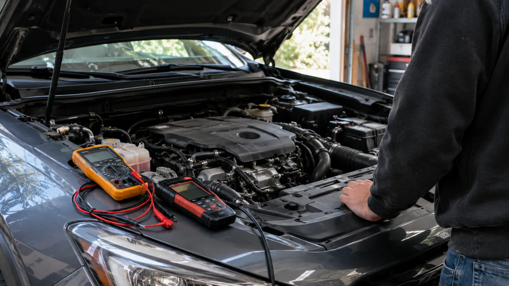
To learn how to test a camshaft position sensor, first identify whether it is a three-wire Hall effect sensor or a two-wire magnetic sensor. A Hall sensor needs a supply voltage, a ground and a signal that switches while the engine turns. A magnetic sensor is checked by its coil resistance and the AC voltage it produces while cranking. Then confirm the result with live scanner data.
This guide gives a separate sequence for each type, the readings to expect, and how to match them to scanner codes. Always check your vehicle's service manual for the exact specification, because supply voltage and resistance values differ by engine.
What you need before you start
Gather a digital multimeter, a scanner that shows live data, a manual, and a few back-probe pins or thin probes. A wiring diagram matters because wire colors change from one engine to the next. Do not guess which wire is which.
Park on level ground, set the parking brake, and turn the ignition off. Keep hands, tools and loose clothing clear of belts and fans whenever the engine is cranking, and follow the manual's procedure for your vehicle.
- Check the battery first. A weak battery drops the sensor supply and the cranking speed, and that skews every reading.
- Inspect the connector for bent pins, green corrosion, and a locking tab that sits fully latched.
- Look at the harness for rubbed insulation, oil soaking and wires near hot exhaust parts.
- Pull codes before touching anything and write them down.
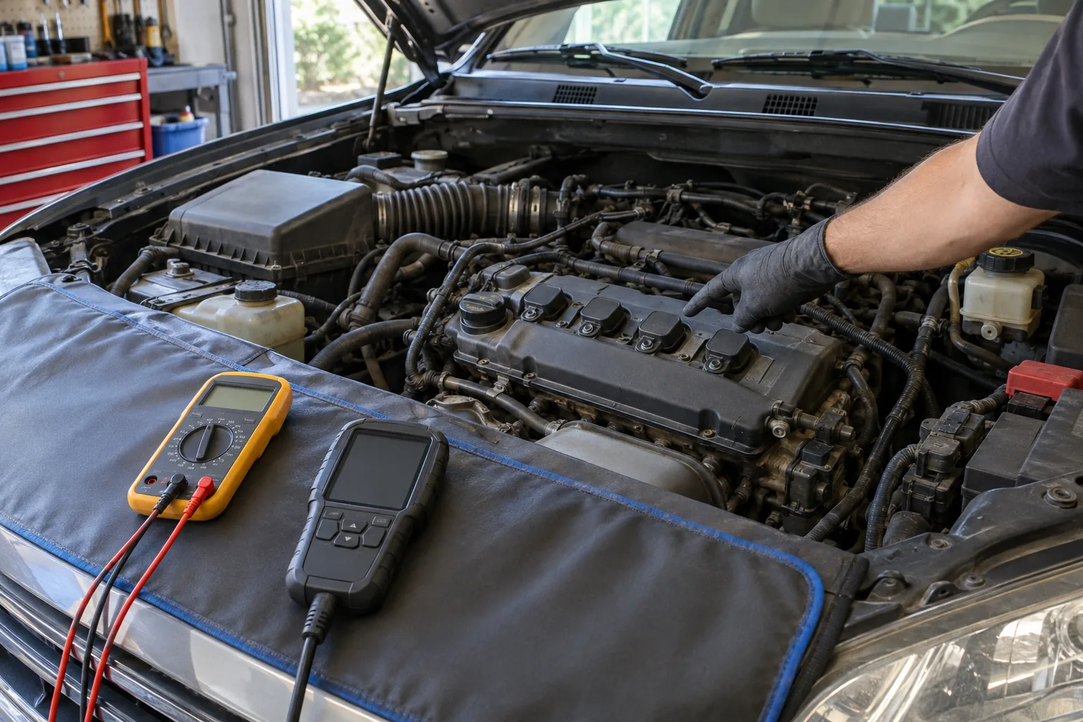
Identify your sensor type
Count the wires at the connector. Three wires usually means a Hall effect sensor. Two wires usually means a magnetic (variable reluctance) sensor. Confirm with the diagram, since some designs differ.
| Feature | Hall effect sensor | Magnetic sensor |
|---|---|---|
| Wires | Three: supply, ground, signal | Two: coil leads |
| Needs power from the vehicle | Yes | No, it generates its own signal |
| Signal type | Square wave, switching low and high | AC wave that grows with engine speed |
| Main meter checks | Supply volts, ground, signal volts | Coil resistance, AC volts while cranking |
How to test a camshaft position sensor with a Hall effect output
This is the answer to how to test a Hall effect sensor: check the supply, check the ground, then watch the signal switch. Do it with the connector plugged in for the signal step, back-probing from the rear of the connector.
Step 1: Check supply voltage
- Unplug the connector and turn the ignition on, engine off.
- Set the meter to DC volts. Put the black lead on a clean engine ground.
- Touch the red lead to the supply terminal from the diagram. Some Hall sensors show a regulated reference near 5 volts, and others show close to battery voltage. Match the figure to your manual.
No supply means the problem is upstream: a fuse, a relay, a broken wire or the engine computer. The article on how to test a relay covers the relay side if your circuit uses one.
Step 2: Check ground
Leave the ignition off. Set the meter to resistance and measure between the ground terminal and the engine ground. A reading near zero ohms is expected. A high reading or OL points to an open ground wire.
Step 3: Watch the signal
Reconnect the plug. Back-probe the signal wire with the meter on DC volts and have a helper crank the engine, or turn the engine by hand if the manual allows it. The signal should flip between a low value near zero and a high value that matches the reference voltage. A reading frozen at either end means the sensor is not switching, or its target wheel is out of position.
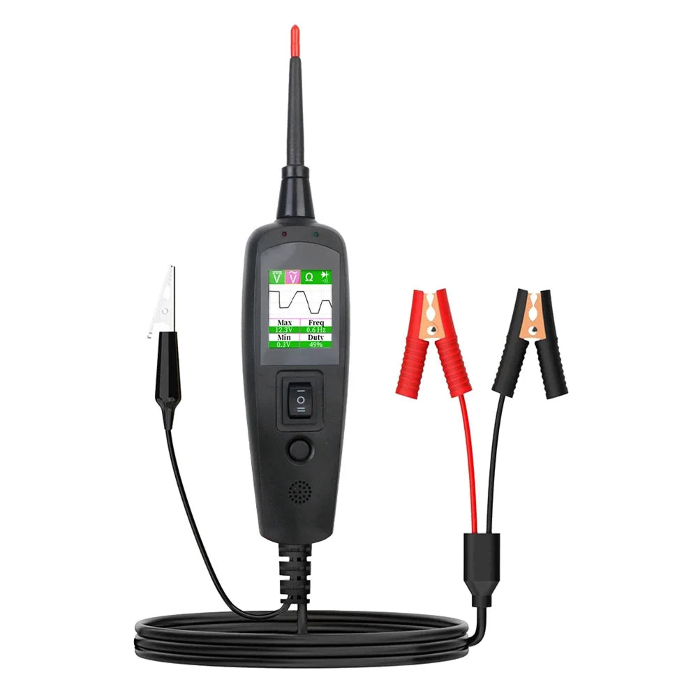
A meter shows the highs and lows but not how clean the pulses are. A tester that shows waveform helps here, and the one below also reads voltage and resistance.
 In this guideFaultLynk$129.99View
The FaultLynk is an automotive circuit tester with a probe and a color display. You clip its leads to the vehicle battery to power it, press the Mode button, and probe the wire to read voltage, resistance or waveform. It works on 12V and 24V systems, which covers cars and heavy trucks. Its polarity LEDs also show red or green when you connect, a polarity check before you take readings.
Testing a two-wire magnetic sensor
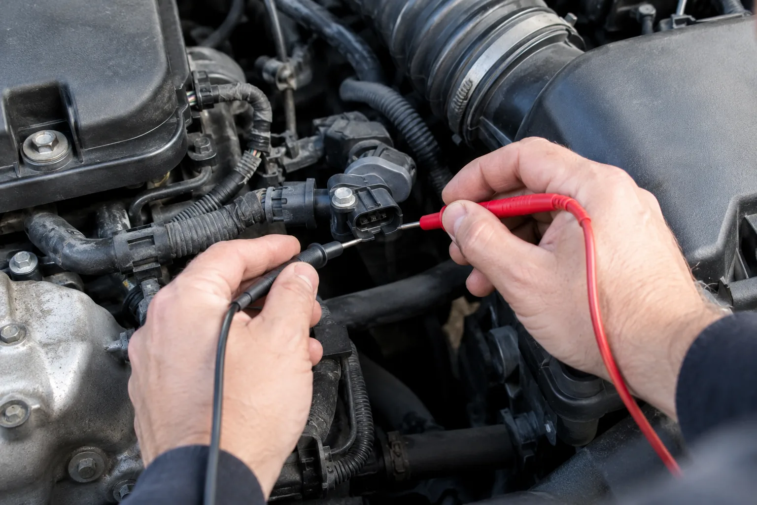
A magnetic sensor has no supply wire, so the checks are different. Start with the coil, then check its output while the engine turns.
- Unplug the connector with the ignition off.
- Set the meter to resistance and measure across the two sensor terminals. Compare the result with the manual's range. An open circuit (OL) or a reading far outside the range points to a failed coil.
- If the sensor has a metal body, measure from each terminal to the body. Any continuity means the coil is shorted to ground. Many two-wire sensors have plastic housings, so follow the manual for this check.
- Switch the meter to AC volts, connect across the two terminals, and have a helper crank the engine. You should see a small AC voltage that rises with cranking speed. No voltage at all suggests a failed sensor or a gap problem.
Resistance changes with temperature, so test a cold sensor and compare with the manual's stated temperature, if it gives one.
Confirm the result with live scanner data
The meter shows whether the sensor works in isolation. The scanner shows how the engine computer sees it. Connect the scanner, turn the ignition on and open the live data list.
- Look for engine speed (RPM) while cranking. A steady RPM reading means the computer is seeing a crank signal.
- Look for a camshaft position or cam sync parameter, if your scanner lists one, and watch it change while cranking.
- Compare the stored codes with your notes. Codes in the P0340 range point to the camshaft sensor circuit, and codes in the P0335 range point to the crankshaft circuit.
- Clear the codes only after you write them down, then see whether they return.
A cam sensor code does not always mean the sensor is bad. Wiring, a timing chain that has jumped a tooth, or a damaged reluctor wheel can set the same code. If the sensor passes and the code returns, check the mechanical side or ask a qualified technician.
Reading your results
| What you see | Likely meaning | Next step |
|---|---|---|
| No supply voltage at a Hall sensor | Fuse, relay, wiring or computer | Trace the supply circuit with the diagram |
| High resistance to ground | Open ground wire | Repair the ground path |
| Signal stays high or low while cranking | Sensor not switching, or target wheel problem | Replace the sensor, then inspect the wheel if it repeats |
| Coil resistance outside the manual range | Failed magnetic sensor | Replace the sensor |
| Good meter readings, code still returns | Wiring, timing or computer input | Check connectors, then timing |
Field note
Wiggle the harness while watching the live data or meter. A signal that drops out when you move the wire points to a connector or wire fault, not the sensor itself.
Testing at home without a multimeter
You can still gather useful evidence. Read codes and live data with the scanner, inspect the connector and harness, and check for oil inside the plug. A visual check of the sensor tip for metal debris or damage also helps on magnetic types.
Without a meter you cannot confirm a sensor failure, so avoid swapping parts blindly. A circuit tester with a probe is a meter alternative, and the guide to electric tester types explains which tool fits which job. You can browse the Electrical & Signal Testers collection for more.
Check the battery before you blame the sensor
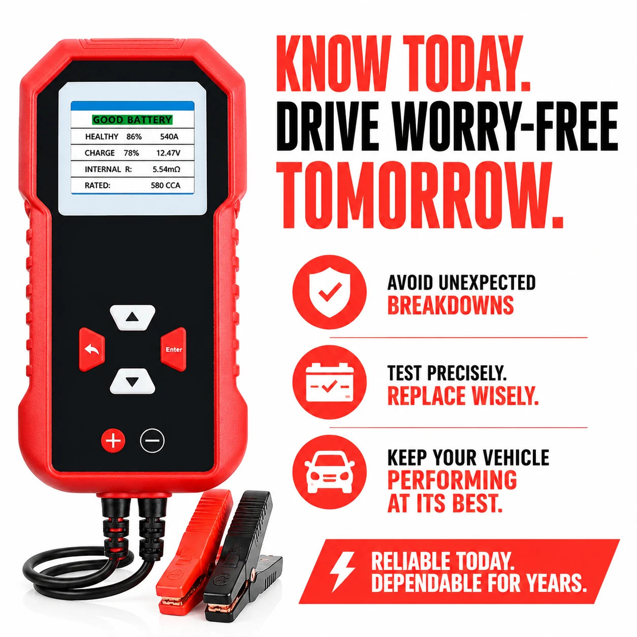
Low system voltage produces odd sensor behavior and slow cranking. If your battery reads low, the article on using a battery charger for a car walks through charging it. A battery tester such as VoltProbe clips onto the terminals of a 12V battery and uses a conductance method to measure voltage, CCA and State of Health. You can check the battery without removing it from the vehicle.
 In this guideVoltProbe$99.99View
Crankshaft sensors and cost
The same methods apply to a three-wire crank sensor: check supply, ground and a switching signal, or use resistance and AC volts for a two-wire one. Warning signs of a failing crankshaft sensor include hard starting, a no-start, stalling, rough running, an erratic tachometer and a check engine light.
Cost depends on the vehicle. The part itself differs by engine, and labor depends on where the sensor sits. Some are on the outside of the valve cover, and others sit behind covers or timing parts. Check the part listing for your engine and the access steps in the manual before you decide whether to do the job yourself.
Common mistakes
- Testing with a weak battery.
- Probing the wrong terminal because wire colors were assumed.
- Piercing wire insulation instead of back-probing.
- Clearing codes before recording them.
- Replacing the sensor without checking the connector first.
Frequently asked questions
Keep reading
 Electrical & Signal TestersElectric Tester Types: Which One for Outlets, Wires and Cars6 min read
 Audio, Connectivity & DiagnosticsWhat Is an Inverter? What It Does and What It Can Run From a Car7 min read
 Inspection Cameras & ScopesVideo Borescopes: How They Work and How to Use One on a Car7 min read