How to Test a Relay: 4-Pin and 5-Pin Automotive Relays
To test a relay, check the coil resistance across pins 85 and 86, then power the coil and confirm the contacts close. This guide covers 4-pin and 5-pin relays, on the bench and in the car.
The Quindrel Team
October 31, 2026 · 8 min read
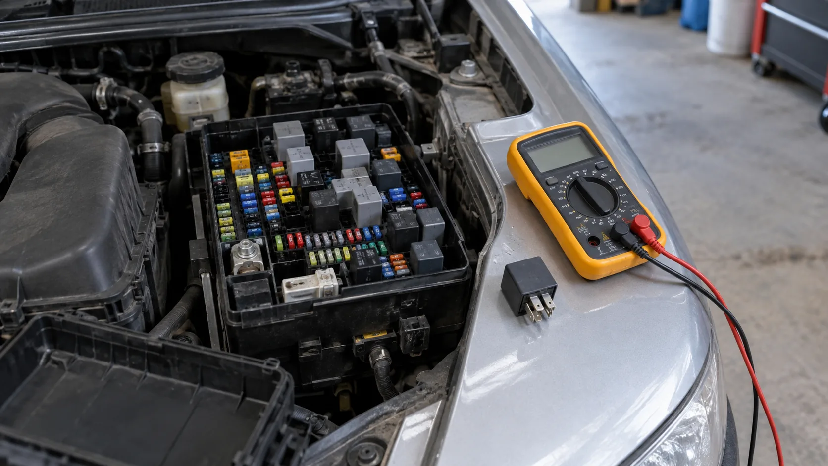
To learn how to test a relay, do two checks: measure the coil with a multimeter, then power the coil from a 12V source and listen for a click while you check continuity across the switched contacts. A relay with a good coil and contacts that close and open on command is working, and the fault is in the circuit around it. The steps below cover 4-pin and 5-pin automotive relays.
A relay is an electrical switch that a small current operates, so a low-current circuit can switch a heavy load such as a fuel pump, horn or cooling fan. When one fails, the load stops working, and a bad relay looks a lot like a bad pump or a blown fuse. Testing the relay tells you which one it is before you buy parts.
Read the pin diagram first
Automotive relays often carry numbers on the base. The numbers follow a common convention, but confirm them against the diagram printed on the relay case, because layouts differ between relays.
| Pin | Name | Role |
|---|---|---|
| 85 | Coil | One side of the coil, often the ground side |
| 86 | Coil | Other side of the coil, often the control power side |
| 30 | Common | Power input to the switch |
| 87 | Normally open (NO) | Connects to 30 when the coil is energized |
| 87a | Normally closed (NC) | Connected to 30 when the coil is de-energized (5-pin relays only) |
4-pin versus 5-pin
A 4-pin relay has one switched output: pins 30 and 87 are open until the coil is energized. A 5-pin relay adds pin 87a, so the common pin 30 connects to 87a at rest and moves to 87 when the coil is powered. It is a changeover switch.
Some relays have a diode or resistor built in across the coil. On those, polarity matters, so connect the coil pins to positive and negative as shown on the relay's case diagram. Diode orientation varies between relays.
Micro and mini formats
Relays come in different body formats, often called mini and micro. The pin spacing and case size differ, so a relay that looks similar may not fit the socket. Match the format and the pin layout on the case, and do not assume that two relays with the same pin count are interchangeable.
What you need before you start
- A digital multimeter with resistance, continuity and DC volts settings
- Two jumper wires, with an inline fuse on the positive lead
- A 12V source, such as a charged car battery
- A test light for the in-car checks
- The relay diagram from the case or the vehicle manual
Switch the ignition off and pull the relay straight out of its socket. If you work near the battery, follow the vehicle manual and disconnect the negative cable first. Keep jumper ends apart from each other and from metal tools while one end is connected to a battery.
Bench test: how to test a relay with a multimeter
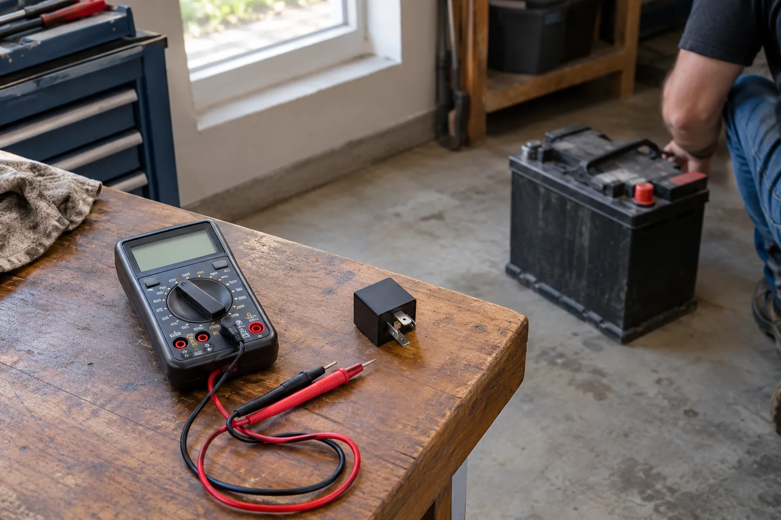
The bench test separates the relay from the vehicle, so any result belongs to the relay alone. Do the steps in order.
Step 1: Check the coil resistance
- Set the multimeter to the resistance (ohms) setting.
- Touch the probes to pins 85 and 86.
- Read the value and compare it with the coil resistance figure printed on the case, if there is one, or listed in the manual.
A steady reading means the coil winding is intact. An open-circuit reading such as OL means the coil is broken and the relay is bad. A reading near zero points to a shorted coil. If the relay has a built-in diode, swapping the probes can give a different reading, which is normal.
Step 2: Check the contacts at rest
Switch the meter to continuity. With the coil unpowered, a 4-pin relay should show no continuity between 30 and 87. A 5-pin relay should show continuity between 30 and 87a and none between 30 and 87.
Step 3: Power the coil
Connect a fused jumper from the battery positive to pin 86 and a second jumper from the battery negative to pin 85, unless the case diagram shows the opposite polarity. You should hear a distinct click as the armature moves. No click usually points to a dead coil or a stuck armature.
Step 4: Check the contacts while energized
Keep the coil powered and test continuity again. On a 4-pin relay, 30 to 87 should now show continuity. On a 5-pin relay, 30 to 87 should show continuity and 30 to 87a should open. Disconnect the jumpers, then check that the contacts return to their rest state.
How to test a relay with a 12V battery and a test light
A 12V battery and a test light can do the same job as the multimeter in Step 3 and Step 4. Power the coil as above, then clip the test light to ground and touch its tip to pin 87 while you feed pin 30 from the positive terminal through a fused jumper. The light should come on only while the coil is energized.
This confirms that the contacts pass current, which a continuity check can miss. A relay can show continuity yet still have burnt contacts that fail with a heavy load, so if a relay passes the bench test but the circuit still misbehaves, try a known good relay of the same type in the socket.
A fuse tester checks fuses only. It has no way to power the coil, so it cannot test a relay itself. You can use it to confirm that the fuse feeding the relay circuit is intact before you start pulling relays.
Dedicated relay testers
A relay tester is a bench device with sockets for common relay formats. You plug the relay in, and the tester powers the coil and shows whether the contacts switch. It does the work of the jumper wires and meter in one step.
A tester is useful if you check many relays, but the multimeter method gives you the same answer. Read the tester's manual for the formats it accepts, and remember that a pass on any bench device can still miss contacts that fail under a heavy load.
In-car test: bad relay or bad circuit
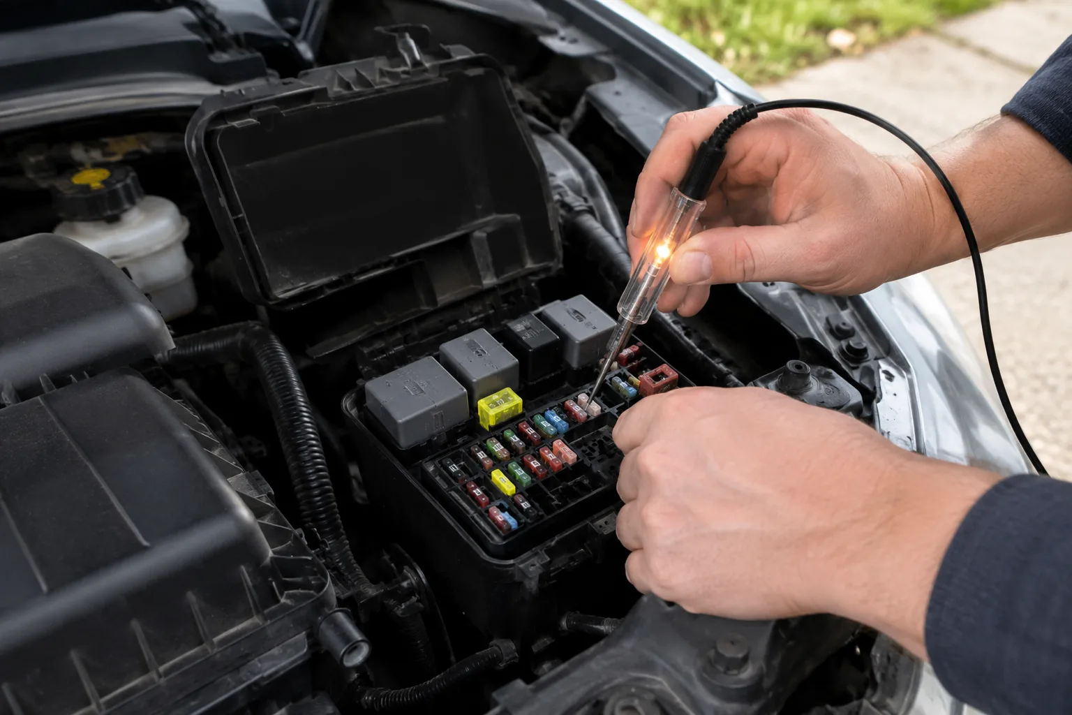
If the relay passes the bench test, check the socket and wiring next. A bench pass can miss contacts that fail under load, so the bypass check below can still point back to the relay. Check the socket with the relay removed, using a test light clipped to a clean ground or a multimeter on DC volts.
| Socket pin | Condition | What you should see |
|---|---|---|
| 30 | Ignition as the manual specifies | Battery voltage |
| 86 | Circuit switched on (key on, switch pressed) | Battery voltage |
| 85 | Circuit switched on | Continuity to ground, or a path through the controller |
| 87 | Relay removed | No voltage |
Missing voltage at 30 points to a blown fuse or broken feed wire. Missing voltage at 86 points to the switch or control side. A bad ground at 85 keeps the coil from completing its circuit.
Bypass check
If voltage is present at the socket, leave the relay removed and bridge socket pins 30 and 87 with a fused jumper. If the load runs, the relay, or its contacts under load, is the fault. If it does not run, check the load and its wiring.
Caution: bridging pins can run a fan, pump or other load directly. Keep hands and tools clear of fans and moving parts, do not bridge fuel pump circuits unless the vehicle manual describes it, and ask a qualified technician if you are unsure.
Voltage readings on a digital multimeter set to DC volts are easiest to read when the battery is in good shape. A weak battery drags the voltage down and can make a healthy circuit look faulty.
Check the battery before you blame the relay
Relay coils need steady voltage to pull in. A low battery can produce a weak click, a chattering relay or dim test lights, all of which look like a failed relay. Measure the battery before you condemn parts.
The VoltProbe is a car battery tester that clips onto the terminals of a 12V battery with copper clamps. It uses a conductance method to read voltage, CCA and State of Health, and the color LCD shows a GOOD, CHARGE or REPLACE verdict plus an alternator and charging system result. The battery can stay in the vehicle, and you take the reading with the engine off.
 In this guideVoltProbe$99.99View
If the verdict reads CHARGE, see how to use a battery charger for a car and retest the relay afterward. More battery and charging tools are in the Battery, Tire & Air Care collection.
Field note
Mark the socket position before you pull a relay, and swap in an identical relay from a circuit you do not need, such as the horn. If the problem moves with the relay, the relay is bad.
Reading the results
| Result | Likely cause | Next step |
|---|---|---|
| Coil reads OL | Open coil | Replace the relay |
| Coil reads near zero | Shorted coil | Replace the relay |
| Coil fine, no click when powered | Stuck armature or weak connection | Recheck the jumpers, then replace the relay |
| Click, but no continuity 30 to 87 | Burnt or pitted contacts | Replace the relay |
| Relay passes, load dead | Fuse, ground, wiring or load | Check the socket voltages |
| Relay passes on the bench, fails in the car | Low battery voltage or poor socket terminals | Check the battery, then inspect the terminals |
Common mistakes
- Using the wrong pin pair: powering 30 and 87 instead of 85 and 86 does not operate the coil.
- Skipping the inline fuse on the positive jumper.
- Reading continuity with the coil unpowered and assuming the relay is bad.
- Ignoring the diode polarity on relays that have one.
- Replacing a relay with one that has a different pin layout. Match the diagram and the amperage printed on the case.
- Testing a relay on a car whose battery is low.
Relays also drive other systems, such as the compressor clutch. If a relay is part of a cooling problem, the car AC diagnosis shows where it fits in the checks.
For any work near the battery, wiring or fuel components, follow the vehicle manual, and ask a qualified technician if you are unsure.