How to Test a Capacitor With a Multimeter, Including AC Capacitors
Discharge the capacitor, remove it from the circuit, then compare the capacitance reading to the label. This guide covers capacitance mode, ohms mode and AC run capacitors, with pass/fail values.
The Quindrel Team
October 29, 2026 · 8 min read
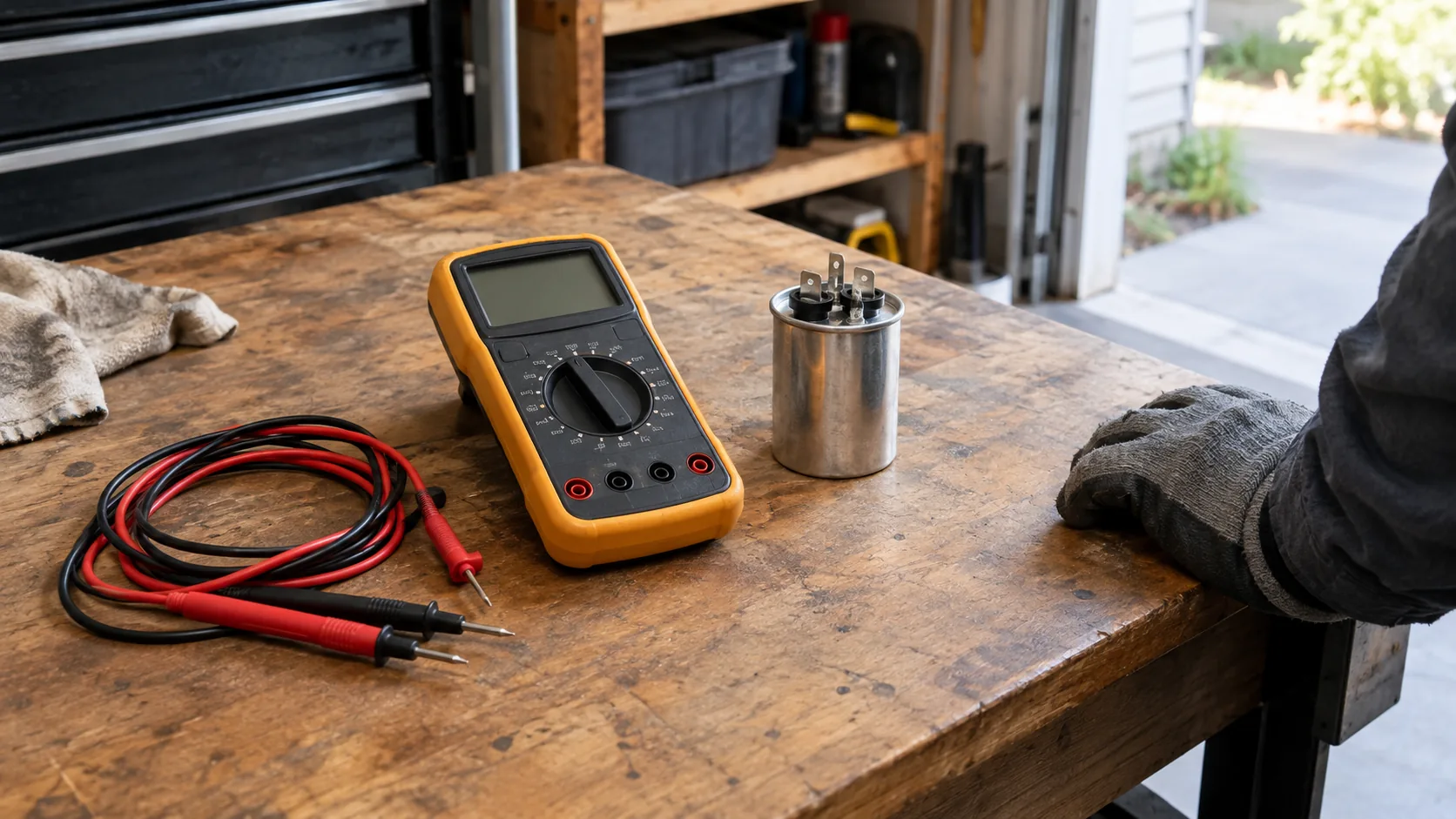
To learn how to test a capacitor with a multimeter, start by cutting power and discharging the capacitor, then pull it from the circuit. Set the meter to capacitance mode, touch the leads to the two terminals, and compare the reading with the microfarad (µF) value and tolerance printed on the label. If your meter has no capacitance mode, an ohms-mode check can show a dead short or an open capacitor, but it cannot confirm the actual value.
This guide gives you a discharge-first checklist, the meter settings, a pass/fail table with a worked example, and the extra steps for an AC run capacitor.
Before you touch it: the discharge-first checklist
A capacitor stores electrical charge and can hold it after the power is off. Large ones, such as those in air conditioners and power supplies, can deliver a hard shock. Assume every capacitor is charged until you have discharged it yourself. Do not open microwave ovens; leave them to a qualified repair technician.
- Turn off the equipment and unplug it, or switch off the breaker and the outdoor disconnect for an AC unit.
- Confirm there is no power with your meter on a voltage range. If you need a refresher, see how to use a digital voltage meter on 12V and household circuits.
- Wear insulated gloves and safety glasses, and keep one hand away from the metal chassis.
- Discharge the capacitor through a resistor with a suitable wattage, using insulated clips or insulated probes across the terminals. Do not bridge the terminals with a bare screwdriver, which can cause sparks and damage the part.
- Check the voltage across the terminals with your meter. Continue only when it reads zero.
- Disconnect the wires from the terminals, noting where each one goes. Photograph the wiring first.
Follow the equipment manual for any model-specific steps, and ask an electrician or HVAC technician if you are unsure about working inside a unit.
What you need and how to read the capacitor
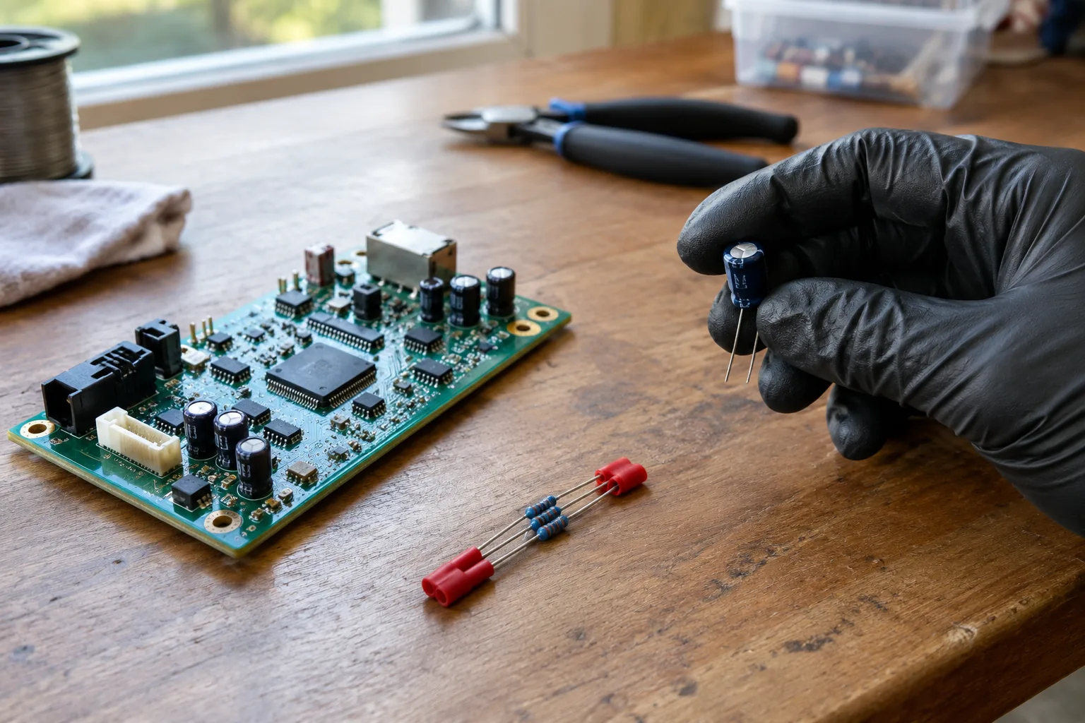
You need a digital multimeter, a pair of test leads in good condition, insulated gloves, a discharge resistor and the capacitor label. Pick a meter with a capacitance setting if you plan to test often. Basic meters without that setting still handle the ohms check described below.
Find the symbol on the dial
The capacitance symbol looks like two parallel vertical lines, one sometimes curved, often sharing a dial position with diode or continuity icons. You may need to press a function button to cycle to it. The unit is the microfarad, shown as µF or uF.
Read the label
The label gives the capacitance in µF, a tolerance, and a voltage rating. The tolerance sets how far the reading may drift from the printed value and still pass. Dual-run AC capacitors list two values, one for each section.
Know the type
- Electrolytic capacitors are polarized, so the red lead goes on the positive terminal and the black lead on the negative marked side.
- Ceramic disk and film capacitors have no polarity.
- Tantalum capacitors are polarized and marked on the positive side.
- Surface mount parts are tiny; you can measure them with smart tweezers or fine-tipped probes.
How to test a capacitor with a multimeter in capacitance mode
This method returns a value you can compare to the label. Use capacitance mode whenever your meter has it.
- Make sure the capacitor is discharged and removed from the circuit, or at least isolated by disconnecting one lead.
- Plug the black lead into COM and the red lead into the jack marked for capacitance, as the meter's manual lists.
- Turn the dial to the capacitance symbol.
- Touch the leads across the capacitor terminals, red to positive on polarized parts.
- Hold steady and wait for the reading to settle. Larger capacitors take longer to display a value.
- Compare the reading to the label value and tolerance.
If the display shows OL or zero on a part that should read a clear value, the capacitor has failed or the meter range is wrong. Try again with clean contacts before you decide.
Pass/fail values: how to read the result
Turn the printed tolerance into a range in µF before you measure. Then the pass/fail decision is a simple comparison.
| Reading | What it means | Action |
|---|---|---|
| Within the label tolerance | Capacitance is in range | Keep the part; look elsewhere for the fault |
| Below the low end of the tolerance | Weak or aged capacitor | Replace with the same µF and voltage rating |
| Above the high end of the tolerance | Out of spec | Replace |
| Zero or OL in capacitance mode | Open or fully failed | Replace |
| Unstable or drifting number | Poor contact or leaking part | Reseat the leads; replace if it persists |
Worked example: a dual-run capacitor
Say the label reads 35/5 µF, with a tolerance of plus or minus 2 µF on the larger section and plus or minus 0.25 µF on the smaller one. These numbers are only an example; use the values on your own label.
| Section | Label | Passing range | Reading | Result |
|---|---|---|---|---|
| C to HERM | 35 µF | 33 to 37 µF | 34.6 µF | Pass |
| C to HERM | 35 µF | 33 to 37 µF | 31.8 µF | Below 33, replace |
| C to FAN | 5 µF | 4.75 to 5.25 µF | 5.1 µF | Pass |
| C to FAN | 5 µF | 4.75 to 5.25 µF | 4.2 µF | Below 4.75, replace |
Read the two sections separately. One section can pass while the other fails, and a failure in either one means the whole capacitor gets replaced.
Signs of a bad capacitor
A bulging top, leaking fluid or a burnt smell are visible signs of failure. Two typical signs in equipment are a unit that hums or does not start, and a motor that runs weakly. Visible swelling is enough reason to replace the part without further measurement.
Testing with ohms mode when there is no capacitance setting
You can test a capacitor with ohms, but the result is a rough check of behavior, not a value. Set the meter to a high resistance range, such as the megohm or highest range available, and touch the leads to the discharged capacitor.
- A healthy capacitor starts at a low resistance, then the number climbs steadily toward OL as it charges from the meter's battery.
- A reading that stays near zero points to an internal short.
- A display that shows OL right away and does not change suggests an open capacitor, though very small values may also look this way.
- A final resistance that ends well short of OL suggests leakage.
To watch the climb a second time, discharge the capacitor again through the resistor, confirm zero volts, then swap the leads and repeat. Charge left over from the meter distorts the second reading if you skip that step. For small ceramic disk capacitors, ohms mode shows little movement because they hold so little charge, so use a meter with capacitance mode when you need confirmation.
| Method | Shows | Limits |
|---|---|---|
| Capacitance mode | Actual µF value | Needs a meter with the setting |
| Ohms mode | Short, open or leakage behavior | No value; weak on small parts |
How to test an AC capacitor
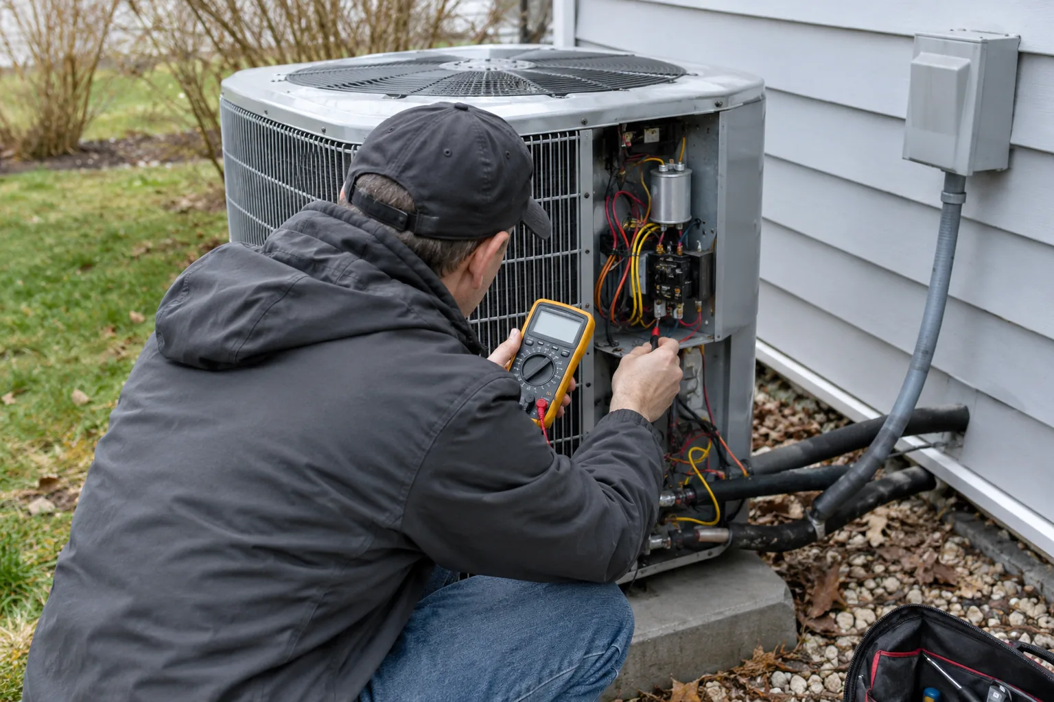
Air conditioner and heat pump units use run capacitors, and sometimes start capacitors, to help the compressor and fan motors. The method matches the steps above with a few additions.
- Turn off the thermostat, the indoor breaker and the outdoor disconnect.
- Open the service panel and locate the capacitor, a metal can with two or three terminals.
- Photograph the wiring, then discharge across the terminals with a resistor. Check for zero volts.
- Pull the wire connectors off with insulated pliers.
- On a dual-run capacitor, the terminals are marked C (common), FAN and HERM. Measure C to HERM for the compressor section and C to FAN for the fan section.
- Compare each reading to the value printed beside that terminal label, using the passing ranges from the worked example above.
A reading below the printed tolerance means the capacitor is weak. A fan capacitor works the same way: measure it across its two terminals and compare with the label. If the can is swollen or oily, replace it without measuring.
Testing in the circuit and common mistakes
Testing without removing the capacitor gives unreliable numbers because other components in parallel can change the reading. Disconnect at least one lead before you measure. If you cannot, consider the result a hint and confirm with the part removed.
Mistakes to avoid
- Measuring a capacitor that is still charged, which can damage the meter or cause a shock.
- Using the voltage-and-ohms jack when the meter's manual calls for a different jack for capacitance.
- Touching the terminals with your fingers while measuring, which adds stray readings.
- Replacing a capacitor with a different µF value or a lower voltage rating than the label.
- Skipping the visual check for bulging, leaks or burn marks.
Other parts you can check with the same meter
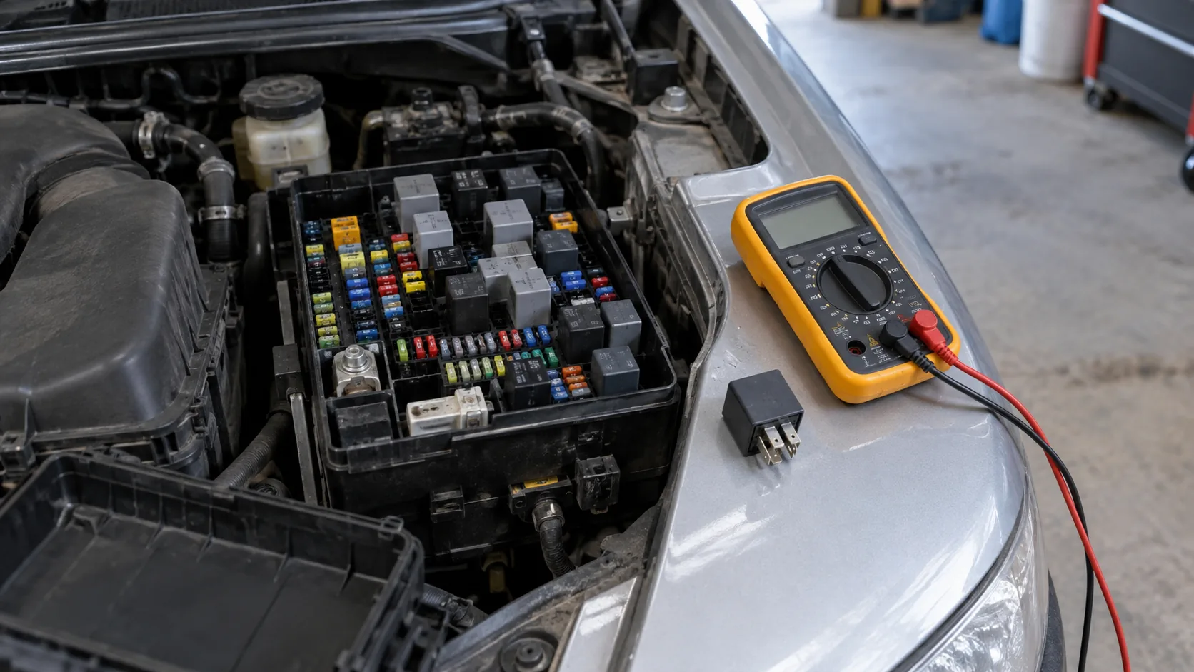
Once the meter is out, other parts follow a similar pattern. For how to test a fuse with a multimeter, remove the fuse, set the meter to continuity, and touch both ends: a beep or near-zero ohms means the element is intact, while OL means it is blown.
To test a relay with a multimeter, measure resistance across the coil pins to see whether the coil is open, then check continuity across the switch contacts with the relay at rest and again with the coil energized. Follow the relay's datasheet or the equipment's service manual, and energize the coil only at its marked coil voltage.
Optional next step: checking a vehicle's 12V battery
If you are troubleshooting a vehicle that cranks slowly or does not start, check the 12V battery and charging system first. A VoltProbe car battery tester clips onto the terminals with copper clamps and uses a conductance method to read voltage, CCA and State of Health. The battery can stay in the vehicle during the test. The color LCD shows a GOOD, CHARGE or REPLACE verdict along with an alternator and charging system result.
 In this guideVoltProbe$99.99View
Field note
Write the label value and tolerance range in µF on a sticky note before you start, and keep the discharge resistor clipped to your bench kit so you do not improvise with a screwdriver.
Care and next steps
Store your meter with the leads coiled loosely and replace leads that show cracked insulation. Keep spare run capacitors matched to the printed µF and voltage rating of the originals. For batteries and charging gear, browse the Battery, Tire & Air Care collection. If a dead battery is the issue, read how to use a battery charger for a car, step by step.
The routine is the same every time: power off, discharge, confirm zero volts, remove, measure, compare with the label. Keep that order and the result is clear to read.